Wiring of mains and motor connections. FC 302 Control Principle 19 363 Control Structure in VVC 20 364 Control Structure in Flux Sensorless FC 302 only 21 365 Control Structure in Flux with Motor Feedback FC 302 only 22 Contents VLT AutomationDrive FC 301FC 302 Design Guide 025-75 kW.
 Danfoss Vlt 5000 User Manual Manualzz
435 Cascade Controller Wiring Diagram 105 436 Fixed Variable Speed Pump Wiring Diagram 106 437 Lead Pump Alternation Wiring Diagram 106 5 Special Conditions 110 51 Manual Derating 110 52 Derating for Long Motor Cables or Cables with Larger Cross-Section 111 53 Derating for Ambient Temperature 111 6 Typecode and Selection 115 Contents.

Danfoss vfd wiring diagram. Optimized for basic operation of pumps and fans the VLT HVAC Basic Drive is supplied with built-in functions that reduce initial costs and increase productivity. 35 Wiring Schematic 16 36 Controls 18 361 Control Principle 18 362 FC 301 vs. A variable frequency drive regulates the speed and operation of an electric motors.
Quick wiring overview from test setup. About Danfoss Contact us Home page. The drive is programmable and offers many features and savings compared to operating a motor from unregulated line voltage.
Danfoss Vlt 2800 Wiring Diagram Danfoss Vfd In Ghaziabad Latest Price Dealers Retailers In Danfoss Vlt 2800 Wiring Diagram wiring diagram is a simplified suitable pictorial representation of an electrical circuit. 7111 Fixed Variable Speed Pump Wiring Diagram 127 7112 Lead Pump Alternation Wiring Diagram 127 7113 Cascade Controller Wiring Diagram 128 7114 StartStop Conditions 129 8 Installation and Set-up 130 81 Installation and Set-up 130 82 FC Protocol Overview 131 83 Network Configuration 132 84 FC Protocol Message Framing Structure 132. Danfoss Vfd With Bypass Wiring Diagram have an image associated with the other.
In this video we used the very popular Mitsubishi D700 series VFD showing single phase and three phase wiring instructions. 44 Wiring Schematic 12 45 Access 14 46 Motor Connection 14 47 AC Mains Connection 17 48 Control Wiring 17 481 Control Terminal Types 17 482 Wiring to Control Terminals 19 483 Enabling Motor Operation Terminal 27 19 484 VoltageCurrent Input Selection Switches 19 485 Safe Torque Off STO 20 486 RS-485 Serial Communication 20. It shows the components of the circuit as simplified shapes and the talent and signal associates in the midst of the devices.
Wiring of control and serial communications. Contents 1 Introduction 3 11 Purpose of the Quick Guide 3 12 Additional Resources 3 13 Document and Software Version 3 14 Certificates and Approvals 3 15 Disposal 3 2 Safety 4 21 Safety Symbols 4 22 Qualified Personnel 4 23 Safety 4 24 Motor Thermal Protection 5 3 Installation 6 31 Mechanical Installation 6 311 Side-by-side Installation 6. Show more Show less.
Learn the basic wiring of variable frequency drives VFD with our electrician Steve Quist. 523 Signal and Power Wiring Consideratio ns for Electromagnetic Compatibility 41 524 Effects of EMI 42 525 Sources of EMI 42 526 EMI Propagation 43 527 Preventive Measures 44 6 Test Procedures 45 61 Non-repairable Units 45 62 Introduction 47 63 Static Test Procedures 47 632 Rectifier Circuit Test 48 633 Inverter Section Tests 48. The panel is a protective enclosure in which the drive and various optional components are assembled and mounted.
Danfoss was the first to introduce a dedicated VFD for the water industry and all of that experience is built into our Drives for maximum performance. The collection that comprising chosen picture and the best amongst others. 15 Block Diagram of the Frequency Converter 4 16 Enclosure Types and Power Ratings 4 17 Approvals and Certifications 4 18 Disposal Instruction 4 2 Safety 5 21 Safety Symbols 5 22 Qualified Personnel 5 23 Safety Precautions 5 3 Mechanical Installation 7 31 Unpacking 7 32 Installation Environments 10 33 Mounting 10 4 Electrical.
Downloads Follow our global channels Keep me updated. The VFDs showed in the video are the D720S 230V single phase and the D720 230V three phase. Automotive Buildings - commercial Buildings residential.
Option panel used in conjunction with a danfoss variable frequency drive vfd or drive. To enable efficient handling of the equipment. Control terminal functions.
Initial programming to verify proper functioning of the drive system. In this video explain how to danfoss vlt micro drive Speed up and down using Remote push button and start stop in remote or auto modePlaylists. 15 block diagram of the frequency converter illustration 11 is a block diagram of the frequency converters internal components.
Detailed tests that must be performed before start-up. Learn about the many applications for VFDs and benefits of choosing Danfoss solutions. The installation guide is intended for use by qualified personnel.
Danfoss Vfd With Bypass Wiring Diagram It also will feature a picture of a kind that might be observed in the gallery of Danfoss Vfd With Bypass Wiring Diagram. We strongly recommend using a certified electrician to set up your VFDs.
 Motor Connection For Clockwise And Counterclockwise Direction Counterclockwise Connection Motor
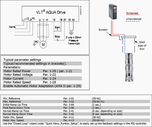
 Using Vlt Aqua Drive In Submersible Pump Application
Danfoss Wiring Diagram Vlt Aqua Winch Switch Wiring Diagram Fisher Wire Yenpancane Jeanjaures37 Fr
 Danfoss Motor Starter Wiring Diagram 125cc Tao Wiring Diagram Hazzardzz Yenpancane Jeanjaures37 Fr
 Deltawerkz Series Hvls Fan 5 Airfoil Blades Design 12ft To 24ft Coverage Up To 2500 Sq Metre Airflow Up To 460 856 Cfm Italy Bonfigl Airflow Motor Airfoil
0 Comments