Including oil gas furnaces air conditioners heat pumps package units air handlers. Armstrong heating equipment heat pumps air handler manuals parts lists wiring diagrams for HVAC equipment.
 New Home Wiring Diagrams Diagram Wiringdiagram Diagramming Diagramm Visuals Visualisation Graphical Electric Furnace Diagram House Wiring
Per foot of 38 od.

Armstrong air handler wiring diagram. Armstrong air conditioning 4SCU13LE Series Pdf User Manuals. Air conditioners boilers furnaces heaters etc. Factory charge contains refrigerant for condenser evapo-rator and 20 feet of 38 line set.
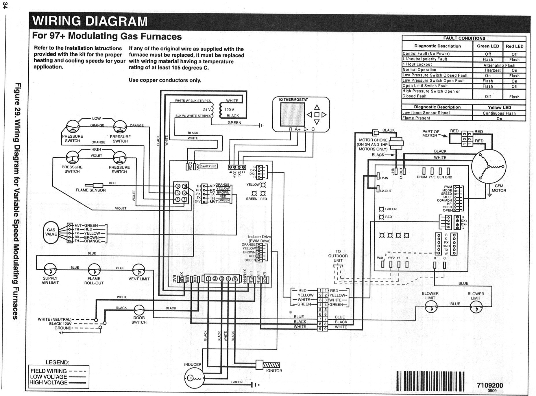
70 l atest editionl in the United States and any state laws and local ordinances including plumbing or wastewater codes. 18 Gauge Standard Single Stage Heat Thermostat Standard AC Condenser AC Contactor 4 This diagram is to be used as reference for the low voltage control wiring of your heating and AC system. Install low voltage wiring from outdoor to indoor unit and from thermostat to indoor unit see Figure 4.
For line set other than 20 feet adjust charge at 060 oz. Adjoining cable courses may be revealed around where certain receptacles or fixtures need to be on an usual circuit. It shows the parts of the circuit as simplified shapes as well as the power and also signal links between the gadgets.
March 19 2019 by Larry A. Always refer to your thermostat or equipment. Install room thermostat on an inside wall that is not subject to drafts direct sunshine or other heat sources.
Every unit delivers Armstrong Airs commitment to quality craftsmanship energy-efficient performance. The AVPTC14 product line may be installed in one of the up- flow downflow horizontal left or horizontal right orientations as. These air handlers are designed for indoor installationonly.
Standard AC with Standard Air Handler and Single Stage Backup Heat Control Wiring Standard Air Handler Wire Size. Water Pump Humidifier user manuals operating guides specifications. Local authorities having jurisdiction should be consulted.
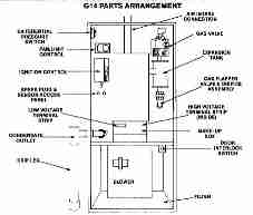
Unit wiring diagrams are located inside the unit access panel. And to help you understand why Armstrong Air is The Professionals Choice. Armstrong Boilers Furnaces Air Handlers Heat Pumps.
Air Conditioning Parts All Air Conditioning Parts. We include immediate downloads of example installation repair manuals and wiring diagrams for air conditioners heat pumps and heating equipment from a variety of manufacturers as well as contact information to obtain the exact manual or wiring diagram for your unit. Please download these armstrong air handler wiring diagram by using the download button or right click on selected image then use Save Image menu.
Technical Services Department at 419 483-4840. Many people can read and understand schematics generally known as label or line diagrams. Either way Armstrong Air has an extensive collection of literature on every piece of equipment we offer to help you learn more.
Liquid line and 12 oz. Wiring diagram is located inside the unit control box cover see also pages 16 and 17 of this instruction. Wiring diagrams help technicians to see how a controls are wired to the system.
Low voltage control wiring are pigtail leads located below the main control box and are color coded to match the connection called out on the wiring schematic. This equipment will perform at installation according to its specifications when installed operated repaired and serviced in strict accordance with the installation and maintenance instructions and using authorized service parts. Here we provide free downloadable copies of installation and service manuals for heating heat pump and air conditioning equipment or contact information for the manufacturers who.
Wellborn Collection of armstrong air handler wiring diagram. ARMSTRONG AIR Replacement Parts By Model and Revision. View online or download Armstrong air conditioning 4SCU13LE Series Installation And Maintenance Instructions Manual.
Wiring diagram is located inside the unit control box cover see also pages 20 and 21 of this instruction. Air Handler Limited Warranty General Five Year Parts Warranty. Model numbers for Armstrong Air products are found on the outside of the unit usually in a lower rear corner.
All units are designed for easy installation and are ideal for closets attics crawlspaces and basements of all sizes. Typical Field Wiring Diagram. Per foot of 1.
View download of more than 506 Armstrong PDF user manuals service manuals operating guides. Figure 3 Wind Barrier Construction Prevailing Winter Winds 24 Wind Barrier Inlet Air Inlet Air Inlet Air Figure 2 Slab Mounting 2 or 2 per 5 slope tolerance away from building structure. The installation of the air handler field wiring warm air ducts etcmust conform to the requirements of the National Eectrical Code ANSINFPA No.
Wiring Harnesses Zone Controls Zone Dampers Sensor Indoor Air Quality All Indoor Air Quality Damper Motors. Armstrong air handler wiring diagram Building wiring representations reveal the approximate areas and also interconnections of receptacles illumination and irreversible electrical services in a structure. A wiring diagram is a simplified traditional photographic representation of an electrical circuit.
Armstrong Air is the professionals choice in home heating cooling. For installations exceeding 100 feet contact the Armstrong Air Conditioning Inc. Professionals choose air handlers from Armstrong Air because of their application flexibility performance and efficiency.
Discharge Air Mounting Slab Ground Level.
 Armstrong Hvac Blower Wiring Civic Wagon Wiring Diagram Jeepe Jimny Yenpancane Jeanjaures37 Fr
 Unique Electric Furnace Blower Wiring Diagram Diagram Diagramsample Diagramtemplate Wiringdiag Thermostat Wiring Electrical Wiring Diagram Electric Furnace
 Control Wiring New Basic Hvac Control Wiring Schema Wiring Diagram Thebrontes Co Unique Control Wiring Thebrontes Co Thermostat Wiring Hvac System Wire
 12 Armstrong Electric Furnace Wiring Diagramarmstrong Electric Furnace Wiring Diagram Wiring Diagram Wiringg Net Reznor Heater Electric Furnace Furnace
 Armstrong Hvac Manuals Parts Lists Wiring Diagrams Armstrong Age Data Tag Decoder
0 Comments